

 By
By Somewhere between unboxing a 3D printer and actually trusting it to produce good parts, there’s a stretch of time that trips up almost everyone new to this hobby. The printer runs, moves, heats up, extrudes plastic — and yet the first few prints tend to come out looking wrong in ways that are hard to explain: stringy, warped, oddly rough, or just slightly off in a way you can’t quite name. That gap is calibration, and it’s often the difference between a printer that “sort of works” and one that produces parts you’d actually want to use.
This guide walks through how to calibrate a 3D printer in a logical order, explaining not just what to change but why it matters and how to tell if it worked. I’m not going to pretend every printer behaves identically, because they don’t. Firmware differs, hardware differs, and the exact menu you’ll be poking through depends heavily on what you own. What tends to stay consistent is the underlying logic — the reasons these settings exist and the problems they’re solving.
If you’re expecting one universal set of numbers to copy and paste, this probably isn’t that article. Calibration is closer to tuning an instrument than following a recipe.
What Does It Mean to Calibrate a 3D Printer?
Knowing how to calibrate a 3D printer starts with understanding what calibration actually means. In plain terms, it’s making sure your printer’s actual behavior matches what it thinks it’s doing. When your slicer tells the printer to move 10mm, extrude 5mm of filament, or heat to 200°C, calibration is what confirms the printer actually does those things accurately.
Here’s the part that surprises a lot of beginners — a printer can be assembled perfectly and still produce bad prints. Assembly is about the physical structure being correct: frame square, belts attached, wiring connected. Calibration is about the numbers behind that structure being accurate. A mechanically sound printer can still under-extrude, print slightly the wrong size, or string badly, simply because the software values controlling it don’t match reality yet.
This is part of why two identical printer models, fresh out of the same factory, can behave a little differently. Small variances in extruder gears, bed surfaces, and sensor tolerances add up, and calibration is how you account for those variances instead of fighting them.
Before You Start: Basic Checks
It’s tempting to jump straight into calibration menus, but doing that before checking basics wastes hours chasing a problem that isn’t actually a calibration issue.
Start mechanical: belts snug but not guitar-string tight, frame screws and joints actually tight (vibration loosens things over time, especially on newer machines). Look at your nozzle — a partially clogged or worn one will sabotage flow calibration before you even begin, since you’d be tuning around a symptom rather than the cause. Check your bed for warping, dirt, or grease, which cause adhesion problems that can look exactly like a leveling issue but aren’t; a quick wipe with isopropyl alcohol saves a lot of guesswork.
Filament matters more than people expect. Wet filament — and most filaments absorb moisture over time, some more aggressively than others — causes popping sounds, inconsistent extrusion, and a rough finish that’s easy to mistake for a temperature problem.
Know your firmware, too. Marlin, Klipper, or a manufacturer’s proprietary system changes where these settings live. Treat any instructions here as the general shape of the process, not an exact script for your machine.
Calibration cannot fix a mechanical problem. If something’s loose, worn, or broken, tuning numbers will only mask the symptom while another one pops up elsewhere.
Bed Leveling and Z Offset
This is often treated as the first real calibration step, and for good reason — a lot of other print quality issues tend to trace back to a bad first layer eventually, even when they don’t look like a leveling problem at first glance.
Manual bed leveling involves adjusting screws or knobs under the bed while checking the gap between nozzle and bed at several points — usually the four corners and center — using a piece of paper or a feeler gauge. You’re aiming for slight friction as the paper slides through, not a total block or a free slide.
Automatic bed leveling uses a sensor to measure bed height at multiple points and compensate in software. This doesn’t replace manual leveling entirely — most systems work best when the bed is already reasonably level, since they correct small variance, not dramatic tilt. Mesh leveling takes this further, mapping the bed at many more points to account for warping across the surface. If your bed dips slightly in the middle, mesh leveling handles that far better than basic four-point leveling.
Z offset is the fine adjustment of exactly how close the nozzle sits to the bed during the first layer, after leveling establishes a baseline. This is one of those settings that looks complicated until you understand what it’s actually changing — it’s not about tilt, it’s about absolute distance.
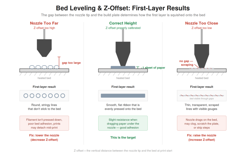
A good first layer has extruded lines sitting next to each other cleanly, slightly flattened, without visible gaps. Gaps or thin, stringy lines mean the nozzle’s too far away. A rough, patchy layer where the nozzle seems to drag material sideways means it’s too close.
If your first layer looks wrong, don’t immediately assume the printer is broken. This is one of the most common calibration issues, and also one of the most fixable — usually with a small Z offset adjustment rather than a hardware fix.
Extruder E-Steps / Rotation Distance
Once your first layer is reliable, the next question is whether the printer is actually extruding the amount of filament it thinks it’s extruding. For anyone learning how to calibrate a 3D printer, getting the first layer right is the best place to start.
Older firmware typically calls this E-steps — the number of motor steps required to extrude 1mm of filament. Some modern printers, particularly those running Klipper, use rotation distance instead, which measures how far filament moves per full rotation of the extruder gear. Different units, same underlying goal: making the extruder’s actual output match its intended output.
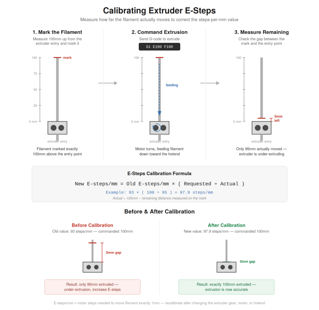
The general process involves marking filament a set distance above the extruder — 100mm is common — commanding the printer to extrude a fixed amount, then measuring how much filament actually moved. If you commanded 100mm and only 95mm fed through, your extruder is under-extruding by that ratio, and the value needs adjusting proportionally.
This matters more than it might sound like at first. Under-extrusion from a miscalibrated extruder doesn’t just create weak prints — it shows up as thin walls, small gaps in solid infill, layers that don’t quite bond properly, and parts that are slightly undersized even though your slicer settings look normal. A small calibration mistake here can show up later as a completely different-looking problem, which is part of why extruder calibration tends to come before flow tuning for most people.
What to do: mark the filament, extrude 100mm through the printer’s controls or your slicer, then measure what’s left above the mark. What to look for: if it’s off by more than a couple of millimeters, adjust the value proportionally — 95mm instead of 100mm means multiplying your current value by roughly 100/95. Repeat after adjusting, since it sometimes takes a couple of passes to land somewhere consistent.
Flow Rate / Extrusion Multiplier
It’s easy to confuse extruder calibration with flow calibration, but they solve different problems — a distinction that doesn’t quite click until you’ve run into a print that’s dimensionally fine but still weirdly weak or blobby. Extruder calibration confirms the motor moves the correct physical amount of filament. Flow rate — sometimes called the extrusion multiplier — is a slicer-side adjustment that fine-tunes how much material is pushed out relative to what the toolpath calls for.
What to do: print a hollow cube with a known wall thickness and measure the actual thickness with calipers once it’s cooled. What to look for: thinner-than-intended walls usually mean flow’s a bit low — nudge the multiplier up a few percent and reprint. Thicker walls, or oozing along wall edges, mean it’s likely too high — nudge it down instead. Small adjustments tend to work better than large jumps.
Incorrect flow is easy to misdiagnose, since the symptoms can look like other problems. Too low, and you get thin, weak walls, visible gaps in top surfaces that should be solid, and parts that measure slightly smaller than the model. Too high, and you get excess material bulging at edges, dimensional inaccuracy in the other direction, and sometimes a rougher surface finish.
PID Temperature Calibration
PID tuning is about stability rather than accuracy in the way flow calibration is. Your hotend temperature naturally fluctuates as it heats and settles — PID tuning adjusts how aggressively firmware responds to those fluctuations so temperature holds steadier instead of oscillating. Unstable temperature can cause inconsistent extrusion, since filament flows a bit differently at 195°C than at 210°C, and sometimes shows up as subtle banding across a print, though it’s not always the obvious culprit.
What to do: most firmware has a built-in auto-tune command — Marlin’s is usually something like M303, Klipper’s is typically PID_CALIBRATE tied to your heater name — that cycles the hotend through adjustments and calculates values automatically. Run it near the temperature you actually print at most, since PID behavior can shift a little between targets. What to look for: the values should get saved, and if your printer’s interface shows a temperature graph, it should look flatter afterward — less of a jagged sawtooth. Double-check your printer’s documentation before running any command directly, since exact syntax and naming vary by setup.
Temperature Calibration
Separately from PID tuning, there’s the question of what temperature is right for a given filament — and this trips people up a bit, since manufacturer ranges are more of a starting point than a guarantee. The same PLA from different brands, or different colors from the same brand, can behave a little differently in practice.
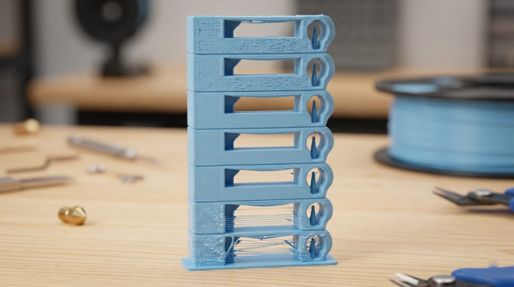
What to do: print a temperature tower — a single print where each section runs at a different temperature within your filament’s rough range, usually stepping down every so many layers. It’s an efficient way to compare results without burning through filament on separate tests.
What to look for: stringing between sections generally points to temperature running too high; poor layer adhesion, a rough texture, or visible under-extrusion generally suggests too low. Somewhere between the two is usually where you want to land — the section with the cleanest surface and least stringing.
If a result looks almost right but not quite, that’s usually worth digging into rather than shrugging off — “close enough” tends to turn into nagging issues once you’re printing something more complex than a test tower.
Retraction Calibration
Retraction is the process of pulling filament back slightly whenever the nozzle needs to travel without printing. Without it, that traveling nozzle tends to ooze, leaving thin strings of plastic connecting points it shouldn’t be connected to — stringing, probably the single most common cosmetic complaint from anyone new to this.
How much retraction you need depends heavily on extruder type. Direct-drive extruders, with the motor right above the hotend, generally need less retraction distance because of the short path. Bowden setups, where the motor is mounted elsewhere and filament travels through a tube, typically need more distance to compensate for that longer path.
There’s no single retraction distance that reliably works across setups — a number that eliminates stringing on a direct-drive printer might do almost nothing on a Bowden system, and could even cause clogging if pushed too far in the wrong context. What to do: print a test object with several small towers, stepping retraction distance up slightly between each. What to look for: the tower with the least visible stringing, without gaps appearing where the nozzle restarts printing — that’s roughly your target.
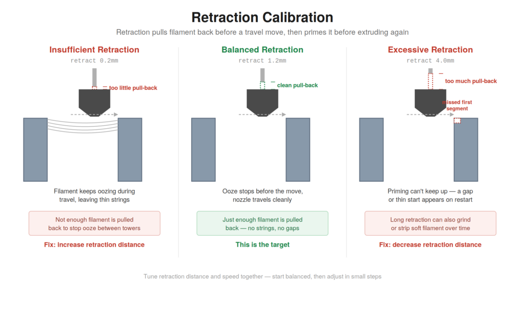
As a rough starting point, direct-drive setups often land around half a millimeter to a couple of millimeters, Bowden setups often need several millimeters more, but treat that as a starting point to test, not an answer to copy outright.
Retraction speed matters too, though it tends to be more forgiving than distance. Too slow, and oozing continues almost as if retraction wasn’t happening. Too fast, and on some setups you risk grinding filament against the extruder gear instead of cleanly pulling it back.
XYZ / Dimensional Accuracy
Once flow and extrusion are dialed in, check whether your printer produces parts that match your CAD dimensions. Print a calibration cube and measure it with calipers along each axis.
Small deviations — half a millimeter or so on a 20mm cube — are often just normal filament behavior or minor flow variance, not a mechanical steps-per-mm problem. Don’t jump straight to changing steps-per-mm to compensate for deviations more likely explained by material behavior. That value is tied to your motor and belt setup and should reflect mechanical reality, not act as a workaround for a flow issue. Larger, consistent errors that scale with size are a stronger signal of an actual steps-per-mm problem worth correcting.
Pressure Advance / Linear Advance
This one tends to confuse beginners the most, partly because the name doesn’t explain itself well. Pressure advance (Klipper’s term) or linear advance (Marlin’s term) compensates for the fact that filament under pressure inside the nozzle doesn’t respond instantly when the printer speeds up or slows down.
Without this compensation, corners can look slightly bulged, and thin features can end up under-extruded right after a fast movement. Pressure advance tells the firmware to anticipate these changes so output stays more consistent through acceleration and deceleration — cleaner corners, steadier extrusion width, fewer acceleration-related blobs. As with most settings here, the exact configuration steps depend on your firmware.
Input Shaping / Resonance Compensation
Ringing, or ghosting, shows up as faint wavy patterns on a print’s surface, usually near sharp corners or direction changes. It’s caused by physical vibration in the printer’s frame — the machine’s own motion creates a small mechanical echo embossed into the surface.
Input shaping is a firmware feature that measures or estimates these resonant frequencies and adjusts motion to cancel them out. Some systems use an accelerometer on the toolhead to calculate compensation values automatically; others rely on more manual tuning, comparing test patterns at different frequency settings.
This is a newer, more advanced step, and not every printer supports it out of the box — it depends on firmware and sometimes extra hardware. If ringing is persistent, it’s worth checking whether your firmware offers this before assuming it’s an unfixable mechanical limitation.
How to Read a Calibration Print
A lot of calibration, if I’m honest, comes down to learning to actually look at what you’ve printed rather than just glancing at it and deciding it “looks fine.”
The first layer tells you about leveling and Z offset — even, slightly flattened lines with no gaps or dragging. Vertical walls reveal flow and extrusion consistency; you want uniform thickness top to bottom. Corners show pressure advance and acceleration behavior. Bridges and overhangs reveal cooling and speed tuning — sagging usually means insufficient cooling or too much speed for the material.
Stringing between separate features points toward retraction or temperature issues. Top surfaces reveal flow rate and cooling together — gaps mean under-extrusion, while excessive roughness often points to cooling or temperature problems.
Learning to connect what you see to what’s likely causing it tends to be more useful long-term than memorizing specific settings — it’s what lets you diagnose a new problem on a printer you’ve never calibrated before.
Common Calibration Mistakes
A few habits tend to slow people down more than the calibration process itself.
Changing multiple settings at once is probably the most common one — adjust temperature, flow, and retraction together, and you won’t know which change caused the result. Using wet filament or calibrating on a dirty, greasy bed introduces problems that look like other issues but aren’t, sending you down the wrong troubleshooting path.
Ignoring mechanical problems and trying to calibrate around them is a losing game; software values can only mask the symptom, not fix the cause. Copying someone else’s exact settings from a forum post, without understanding why those numbers worked for their setup, often leads to confusion — their Z offset or retraction distance was tuned for their machine, not yours.
Not recording previous values before changing them causes real headaches later, and calibrating at unrealistic temperatures skews results in ways that won’t hold up in normal printing.
And assuming one calibration test fixes everything permanently is probably the biggest misconception of all. Calibration isn’t really a single event — it’s closer to ongoing maintenance than a one-time task you check off.
A Practical Calibration Order
If you’re wondering how to calibrate a 3D printer from scratch, a sensible sequence looks something like this – though “sensible” is doing some work there, since plenty of people get decent results tweaking things in a slightly different order too:
Mechanical check → Bed leveling and Z offset → Extruder calibration → Temperature tuning → Flow rate → Retraction → Dimensional accuracy → Pressure/Linear Advance → Input Shaping
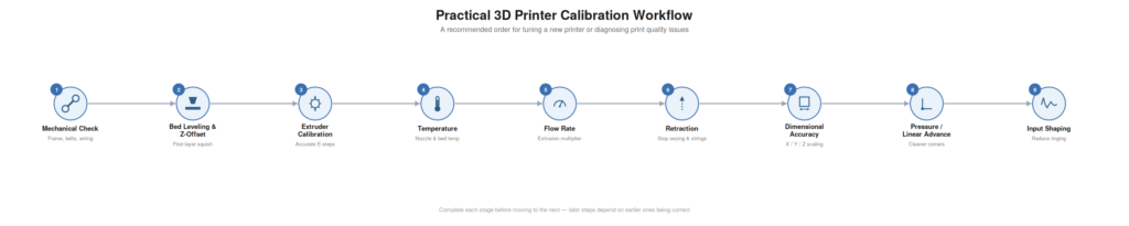
This order isn’t arbitrary, even if it’s not the only workable one. Each step tends to build on the one before it, and calibrating out of sequence often means redoing earlier work. There’s not much point tuning flow rate on an extruder that isn’t extruding the right amount to begin with — you’d just be compensating for one error with another. Similarly, retraction tuning on unstable temperature is a bit like chasing a moving target, since stringing behavior shifts with temperature.
This is where patience matters more than speed. It’s genuinely faster in the long run to work through this order deliberately than to bounce between settings hoping something eventually clicks.
How Often Should You Calibrate a 3D Printer?
Not every change requires starting the whole process over, which is good news, since full recalibration is time-consuming.
Switching filament brands or materials — say, PLA to PETG — usually calls for retuning temperature and possibly flow and retraction, since materials behave differently even at similar nominal settings. Switching nozzle sizes or replacing a worn nozzle changes flow characteristics enough that flow rate, and sometimes pressure advance, need rechecking.
Moving the printer to a location with different ambient temperature or humidity can shift things enough to warrant a check. Changing your build surface usually means re-leveling and rechecking Z offset, since surface height and texture affect first-layer behavior directly. Changing extruder hardware, modifying firmware, or replacing major mechanical components are the clearest triggers for a full recalibration.
Day-to-day printing with the same filament, nozzle, and build surface generally doesn’t need constant recalibration. Once a printer’s dialed in for a given setup, it tends to stay reasonably consistent until something physical changes.
You Might Also Like
- 3D Printing Innovations: What’s Actually Changing and Why It Matters
- Raspberry Pi Home Automation: What I Learned After 6 Months
- Best Home Automation Light Switches for Beginners (2026)
- Beginner’s Guide to Mini RC Drift Cars (Real Experience After 3 Years)
- Drone with Thermal Camera — My Real 6-Month Experience (Mistakes Included)
- How to Become a Drone Pilot — What Actually Happened When I Tried It
- Agricultural Drone — What Actually Happened My First Season – 2026
Final Calibration Checklist
Before trusting your printer for normal use, it’s worth confirming a few things:
- Bed is level and Z offset produces a clean, even first layer
- Extruder moves the correct amount of filament when commanded
- Flow rate produces accurate wall thickness on a test print
- Temperature is stable and appropriate for your filament
- Retraction minimizes stringing without causing gaps or clogs
- Printed dimensions match CAD dimensions within a reasonable tolerance
- Corners and acceleration-heavy areas look clean, not bulged or thin
- Surface quality looks consistent, without unexplained ringing or roughness
If most of these hold up across a few different test prints, not just one lucky result, your printer is in reasonably good shape for regular use.
Wrapping Up
Learning how to calibrate a 3D printer isn’t really about hunting down one magical set of numbers that unlocks perfect prints forever that unlocks perfect prints forever, even though it’s tempting to hope for exactly that. It’s more about understanding how your specific printer, filament, hardware, and slicer settings all interact — and accepting that this relationship shifts a little every time one piece of that equation changes.
That probably sounds like more work than you were hoping for, and honestly, it kind of is. But it’s not complicated work, just deliberate. Most of it comes down to changing one thing, printing a test, actually looking at the result instead of skimming past it, and adjusting from there. The printers that feel effortless later tend to be the ones someone spent a bit of unglamorous time tuning early on — not because they got lucky with the settings, but because they got used to reading what the printer was telling them.
If there’s one habit worth holding onto through all of this, it’s restraint. Change one setting at a time. Actually test it before moving on. Write down what you changed before you change something else. It’s slower than guessing your way there, but it’s the difference between genuinely understanding your printer and just hoping the next print turns out okay.